
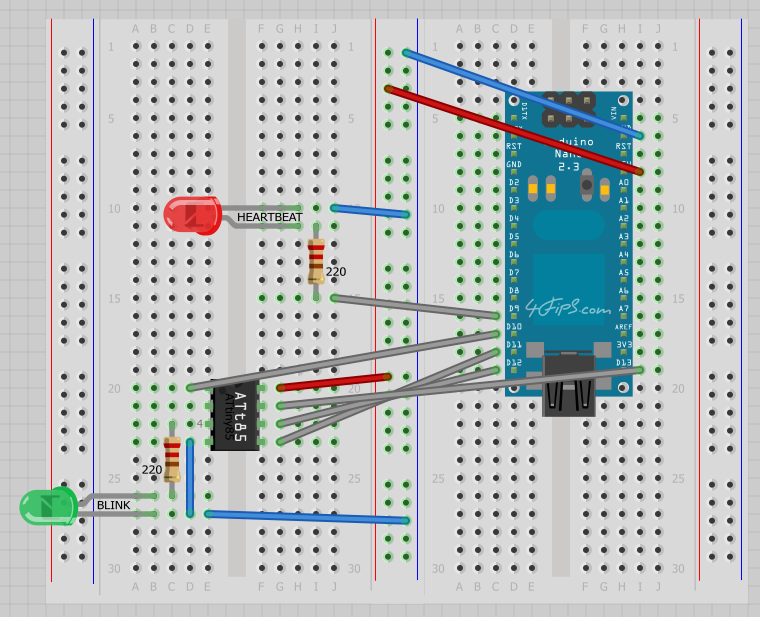
Step 1 - Build the circuit:
The image blow shows the wiring. Our goal is to program the ATtiny85 to blink the green LED. Note that the red LED is for diagnostics only, it's so-called heartbeat that indicates whether Arduino has been correctly set up as a programmer, we will talk about that later...
Step 2 - Introduce ATtiny boards to the Arduino IDE:
First, download attiny-master.zip, then copy the attiny directory from:
attiny-master.zip/attiny-master/attiny/*
into the Arduino IDE installation directory:
<arduino_ide>/hardware/attiny/*
After restarting Arduino IDE, you should see new boards ready to use:

Step 3 - Setup the Arduino Nano as a programmer:
From the main menu select: File / Examples / ArduinoISP

Then upload the sketch. After that, the red LED (heartbeat) should start winking.
Step 4 - Upload a program into the ATtiny85:
Now open a sketch that you are going to upload into the ATtiny85. In our case we are using a modified Blink example that uses Pin 4 (which is actually Pin 3 of the ATtiny85 package).
Then select: Tools / Programmer / Arduino as ISP

also select: Tools / Board / ATtiny85 (internal 1 MHz clock)

Now upload the sketch, the green LED should start blinking...